Brisbane 2032: Creating lasting impact through transformative infrastructure
Aurecon shares insights on how the 2032 Brisbane Games can deliver legacy infrastructure and lasting economic, environmental and community value.


Change your location to view content tailored for you.
Tunnels play a critical role in the ongoing delivery and maintenance of the infrastructure required to support our modern world. We have been constructing tunnels in our cities since the nineteenth century.
Today, tunnels are an increasingly necessary part of our road and rail networks and continue to be employed to support our water, sewer and utilities systems.
During the time we have been constructing modern tunnels, we have seen some revolutionary developments, yet some aspects of tunnelling are the same as they were when the first tunnels were being built by pioneering engineers. This article discusses the evolution of tunnelling and where we are now in delivering modern solutions.
The original tunnels were excavated by drill and blast or hand mining methods and although the equipment may have changed with the inclusion of mechanised drilling and ground excavation machinery, we still build tunnels with similar methods today.
However, the single most dramatic change has been the introduction of the Tunnel Boring Machine, known in the engineering profession as TBMs. In this method, the entire face is cut with a circular head engaging all of the face as it turns.
In 1959, the Hydro-Electric Commission of Tasmania purchased the first Australian hard rock TBM for ,000. The project was a water tunnel and the best week’s tunnelling excavation advance was 229m, claimed to be a world record for any tunnel at that time. This great improvement in the excavation rate was offset by weeks of poor performance due to machine maintenance and repairs or due to difficulty supporting poor ground conditions.
By 1970, several hard rock TBMs were being used in Australian cities for water and transportation projects. By the mid-1990s, the bentonite shield method of TBM excavation was introduced to Australia, which allowed the use of TBMs in not only rock but in poor and mixed face ground conditions.
Some researchers in the 1970s considered that new excavation techniques would arrive in the future such as rock melting, jetting or chemical breakage. Others predicted that rates of excavation would increase.
The reality for the tunnelling industry is that TBM best week advance rates have not greatly improved over the years. However, what has happened is that the number or incidence of poor weeks has improved, so the gap between best and worst has reduced. Overall, this has resulted in projects as a whole being excavated faster and cheaper.
The TBM machines we employ are much more reliable and average advance rates of 100m per week are now routine. Closed face machines are now common and mixed face conditions can be handled, while rates of up to 400m have been achieved.
Some of the anticipated technological advances for tunnel construction have not eventuated. The mechanisms used in the 1960s are still the same as now, except that today’s machines are bigger and stronger due to advances in metallurgy and manufacturing (see Figure 1).
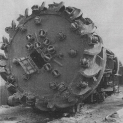
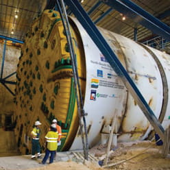
Figure 1. Left: The Poatina machine from 1961. Right: The Clem7 machine from 2008. Both machines use disc cutters.
In terms of the tunnel ground support, the introduction of TBMs has facilitated a move towards one-pass precast concrete linings and away from temporary support installed as directed by a geologist/tunnel engineer bespoke to the ground conditions. The former is suited to a factory style of installation, in that it is cyclical and programmable. The latter may be more cost efficient on a metre by metre basis but the cost and management of the surveillance operation is becoming less attractive.
Another advantage of the precast lining system is that it can be made watertight on installation, which avoids the hydrogeological issues which are becoming critical in many cities.
In the late 1960s, public outcry over “the Motorway Plan” in London prevented a network of surface freeways from being built. Similar public sentiment progressively prevented the completion of freeway networks in Australian cities.
Figure 2 shows the planned Eastern Distributor in Woolloomooloo, Sydney which would have involved the removal of all houses within the proposed route.
The initial scheme design was scrapped and in the late 1990’s, the Sydney’s Eastern Distributor was constructed using tunnels rather than an above ground road system. The result was that the majority of houses and buildings along the projects corridor remain intact today.
The Eastern Distributor in Sydney is just one example of how both roadways and rail lines have been constructed by tunnel rather than what would have traditionally been built at or above ground level. Over the past 20 years tunnelling projects have allowed cities in Australia (and around the world) to avoid the surface or to avoid the construction of obtrusive structures.
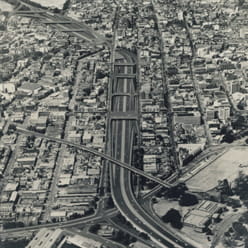
Figure 2. Render of the originally proposed Eastern Distributor, Sydney, Australia.
Tables 1 and 2 lists some of the major Australian tunnel projects of the past 20 years. Many of the road tunnels listed above represent the “missing link” in a freeway plan which was drafted in the 1960s and which have had to wait until the tunnel solution can be found.
The trend which is evident from these lists is towards longer road tunnels. The Airport Link project at 7km is now the longest road tunnel in Australia and one of the longest urban road tunnels in the world. (The longest road tunnel in the world is the Laerdal Tunnel in Norway at 24.5km).
Not only are we seeing these changes in Australia but New Zealand is also planning to deliver major transportation projects using tunnel solutions.
| City | Mode | Project | Tunnel Beneath |
|---|---|---|---|
| Sydney | Road | Sydney Harbour Tunnel | Sydney Harbour – avoided Greenwich-Balmain bridge |
| Sydney | Road | Eastern Distributor | Woolloomooloo |
| Sydney | Rail | New Southern Railway | Airport operations, Mascot, Waterloo, Redfern |
| Sydney | Road | Cross City Tunnel | CBD |
| Sydney | Road | Lane Cove Tunnel | Lane Cove |
| Sydney | Road | M5 East Tunnel | Arncliffe |
| Sydney | Rail | Epping Chatswood | Chatswood, Roseville, North Ryde, Epping, Lindfield |
| Sydney | Road | M2 Tunnel | Epping |
| Brisbane | Rail | Brisbane Rail Tunnels | CBD, Fortitude Valley |
| Brisbane | Road | Clem7 | Fortitude Valley, Kangaroo Point |
| Brisbane | Road | ICB | RNA Showgrounds |
| Brisbane | Busway | South East Busway | Southbank station, Vulture St, Buranda St |
| Brisbane | Busway | Boggo Rd Busway | Boggo Rd Jail |
| Brisbane | Road | Airport Link | Wooloowin, Lutwyche |
| Brisbane | Road | Northern Link | Milton, Auchenflower, Toowong |
| Melbourne | Road | CityLink | Botanical Gardens, Richmond |
| Melbourne | Road | EastLink | Mullum Mullum Creek |
| Perth | Rail | Metro | CBD |
| Perth | Road | Graham Farmer Freeway | Northbridge |
| Adelaide | Road | Crafers Freeway | Mount Barker |
Table 1. Urban transportation tunnel projects in Australia 1990-2010.
| City | Mode | Project | Tunnel Beneath |
|---|---|---|---|
| Sydney | Road | M4E | Inner western suburbs |
| Sydney | Road | F5-M2 | Wahroonga |
| Sydney | Road | Sydney Metro | CBD |
| Brisbane | Rail | Cross River Rail | CBD, Woolloongabba, Fairfield |
| Melbourne | Rail | MM1 | CBD, North Melbourne |
| Melbourne | Road | WestLink | Footscray |
Table 2. Planned urban transportation tunnel projects in Australia.
While tunnel equipment and technology has improved, the public has become less tolerant of the environmental effects of tunnelling. Often tunnelling is a 24 hour activity and noise at the worksite can be a critical issue. In 1972, the contractor on the Eastern Suburbs Railway was served with an injunction preventing 24 hour operation. Since that time, many city worksites have incorporated acoustic noise sheds which also have served to control dust.
In addition to this control, spoil can be stored during night operations to then be trucked offsite during the day (Figure 3).
A particular issue in modern tunnelling has been the focus on hydrogeology. The tunnel’s effect on the groundwater has driven design solutions in Melbourne and Brisbane recently. At the EastLink tunnel in Melbourne, the need to prevent drawdown of the watertable and maintain environmental flows to Mullum Mullum Creek was critical. The topography meant that the creek ran above the tunnel itself which led to the tunnel being designed and constructed as a completely watertight structure. Design specifications required very tight allowable leakage into the tunnel once was completed.
The solution was a hybrid precast/cast-insitu lining solution (Figure 4). However, other tunnels such as Clem7 (Brisbane) and Airport Link (Brisbane) have adopted the full segmentally lined solution installed behind a TBM.
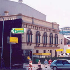
Figure 3. Acoustic and dust shed at Cross City Tunnel, Sydney, Australia.
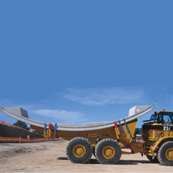
Figure 4. EastLink Tollway construction Victoria, Australia – precast invert segment.
Other environmental issues which are impacting on tunnel construction include the vibration caused by both mechanical and TBM tunnelling, known as regenerative noise. This was carefully monitored at the Clem7 site and will be monitored at the Northern Link project. The vibration is temporary, with limited intensity and short term as the tunnels move quickly past each residence. Because the vibrations may induce sleep disturbance, the issue is often handled by direct consultation with the affected residents.
Finally, the issue of ventilation outlets can be a matter for public concern, as was the case at Sydney’s M5 East tunnel. The purpose of the ventilation outlets is to elevate the outflow of spent air from the tunnel’s ventilation system so that this air can be mixed with fresh air in a controlled manner. This issue is reducing with every year, as the vehicle fleet improves. With the increasing use of electric and hybrid vehicles it can be anticipated that this issue might disappear in time.
Aurecon's Dr Harry Asche gives an update to ABC Radio in June 2021 on the numerous tunnelling projects being constructed in Sydney and why different tunnelling methods are used for different locations and ground conditions.
Listen to this podcastRevolutionary changes in urban transportation tunnels are coming from the vehicles using the tunnels and the systems which can control them. Road and rail vehicles are changing rapidly with a potential knock-on effect in terms of the safety and ventilation systems required to be fitted to the tunnels (Table 3).
Within 20 years, it is likely that a substantial reduction in the capital cost of constructing a tunnel will be made due to a reduced need to provide ventilation equipment and ducts, and due to a reduced need to provide for cross passages and emergency walkways. Further in the future it is possible that lane width could be substantially reduced and that more lanes could be retrofitted to existing tunnels.
| Category | Trains and metro systems | Cars/Trucks |
|---|---|---|
| Pre 1970 | Train drivers Open platforms Rolling stock with fire load |
No emission controls Fixed signage/speed limits Enforcement by police vehicles Vehicle control by levers/hydraulics |
| Current international practice | Automatic train control Platform screen doors Fire load controlled rolling stock Centralised maintenance at stations |
Emission controls/improved fuels/hybrid vehicles Variable message signs/variable speed limits Speed cameras/point to point systems/CCTV Antilock braking system – electronic intervention in vehicle control |
| New/experimental/future | Driverless trains | Reduced fire loan in cars Electric vehicles (zero emissions) Collision prevention Hands off driving |
Table 3. Changes in vehicles and systems.
Similar to the situation in tunnelling construction, no major breakthroughs have occurred in tunnelling design since the 1970s. That said, incremental advances have taken place in the tools and methods, mostly on the back of the enormous advances in computers.
In 1970, the finite element analysis method had begun to be applied to tunnelling design, although each problem took weeks to set up and run. Using finite element models is now routine and powerful packages allow the tunnel engineers to solve problems in minutes (not weeks). The models available to the designer can now incorporate all properties of materials and ground, 3D features and water flow. (See Figure 5 for some examples of models.)
However, what has not changed is that the characterisation of the ground remains dependent on an expensive and time-consuming ground investigation, and that the development of relevant and useful design models relies on experience and on well judged model inputs.
One advantage now is that each of the cities in Australia has a database of previous experience in tunnelling which allows modellers to compare their outputs with actual sites.
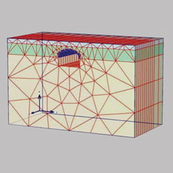
Figure 5a. Canopy tube model (CCT).
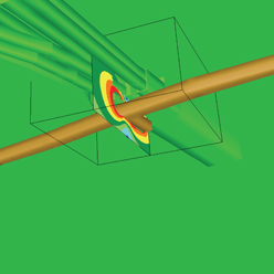
Figure 5b. Stress beneath Town Hall Station (CCT).
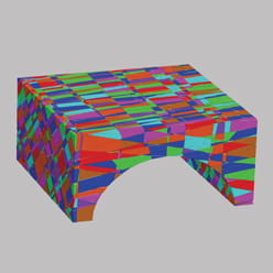
Figure 5c. Rock block model (EastLink).
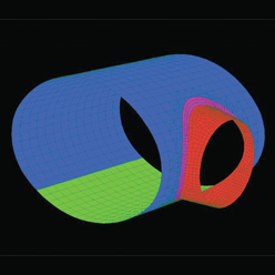
Figure 5d. Cross passage lining model (EastLink).
So what does the future hold for tunnels? The summary below lists a number of possible future trends, including some speculative suggestions:
Contributing author & reviewer: Harry Asche
Aurecon shares insights on how the 2032 Brisbane Games can deliver legacy infrastructure and lasting economic, environmental and community value.
How engineering and construction projects are evolving to champion biodiversity, through early planning, advanced technologies, and ecosystem stewardship.
This fact sheet compares the community and environmental impacts of wind farm projects, and how ecologically sensitive design can deliver better outcomes.